
Tweet
| Navigation |
| Home |
| Site map |
| Articles |
| Contact |
| Links |
| Forum |


Dome structural analysis basicsAnalysing a structure to find out how much load it can withstand before actually building it can save a huge amount of time, effort and materials not to mention being able to sleep at night knowing your structure won’t fall down if it gets a bit windy. Having said that the cost of employing a structural engineer to analyse and calculate the mechanical, wind and snow loads on a structure can also be pretty costly and time consuming. Guessing what size materials you need or copying what someone else has done is still what most people do, but you’re left with little or no idea what loads a structure will carry, when or where a failure will occur or if there is a better, more cost effective way to build in the first place. Basic principals of structural analysis: Compressive load – crushing force, we’ll use red lines in diagrams to show this. Tensile load – stretching force, we’ll use blue lines to show tension Division of load or force – four legs on a table divide the weight between them. Multiplying load or force – Pulleys and levers can multiply a force certain structural layouts can also do this.We can demonstrate all of these forces in one simple diagram. Below we have a simple triangle frame held on two supports with a force of 50 lbs applied to the top. The triangle side supports have a compressive force of 29 lbs, the bottom support has a tensile load of 15 lbs resulting in a 25 lb load on each bottom corner. 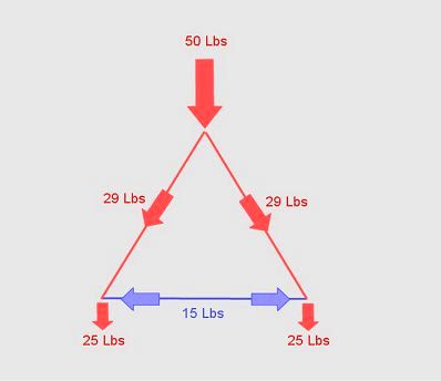 If we change the shape of the triangle frame you will notice a big change in the loads. We still have a 50 lb force at the top and this is transferred equally to each bottom corner but the tensile and compressive loads in the triangle frame have greatly increased, the only alteration was to lower the height of the triangle. 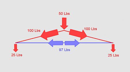 We can apply this simple concept to a wide range of structural elements to work out roughly what sort of forces are acting on a structure, lets start with a typical 3 frequency dome and compare it to a typical house to get an idea of what''s involved. 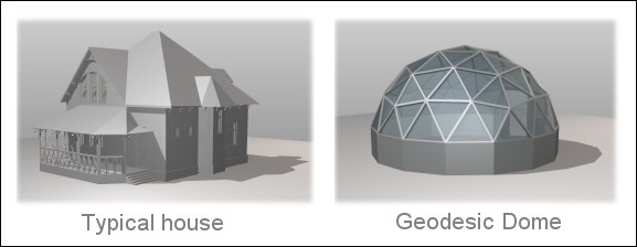 Wind analysis: Load analysis: Conclusions: We’ve dealt with basic some of the basic concepts of structural analysis so now we’ll take a look at a 3 frequency geodesic dome in a little more detail. 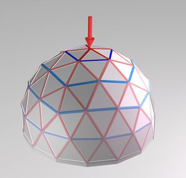 At the point where we’ve placed the downward force the hub is under compression however you will notice a series of tension rings circling this point all the way down the dome, all other hubs have a combination of tension and compression, 2 struts under tension and 4 under compression. Greatest tensile and compressive stress is close to the applied force. This is a very simple example but it gives a practical insight into what forces are acting on the hubs so we can do some real world testing. Common mistakes when testing hub designs: 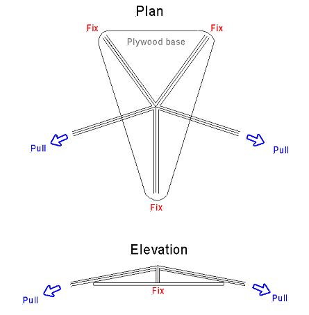 To structural analysis a pentagon hub, fix three struts to a solid plywood base then apply a pulling force to the remaining two loose struts. Pull both together directly away from the hub. This will structural analysis the hub under compressive and tensile loads, if you can measure the force needed to break the hub this will give you some figures to work out wind and snow load capabilities for your dome. Test a strut by hanging a progressively larger weight in the middle of the longest strut until it also fails; what we want is for both elements to fail under similar loads so the structure doesn’t have over engineered elements that waste materials or weak elements that could compromise the structure prematurely. I’m currently writing the next article that goes into more detail and has a 3v dome structural report. |
|
 |
|
| [ comments 2 ] |
comments will be accessed through the forum in the new site design (coming soon)
11766